An Air Cooled Process Chiller removes heat from process equipment and rejects it into the surrounding air. A refrigeration circuit cools circulating fluid, while fans move air across the chiller’s condenser. A pump then sends the cooled fluid through pipes to equipment that needs temperature control. The setup is common in manufacturing, plastics processing, food production, and laboratory systems. It can support equipment such as injection molding machines, lasers, and industrial mixers. In practical terms, it helps keep process temperatures steady as operating conditions change.
The label can sound simpler than the installation is. Selecting a unit requires more than matching a listed cooling capacity to a machine. Engineers typically consider the actual heat load, fluid flow, required temperature, site conditions, and expected operating hours. Warm outdoor air can reduce a chiller’s available cooling capacity, and restricted airflow may affect performance. Fans also produce sound, which matters when equipment sits near work areas. Details count. Routine inspection of condenser coils, filters, fluid lines, and electrical connections can help identify problems before they interrupt production. A suitable system should be evaluated against the process and its environment, not chosen by headline specifications alone. Even careful planning has limits: loads can vary, and real installations may reveal assumptions that need review. Understanding how an Air Cooled Process Chiller works is a useful starting point for comparing options, planning installation, and maintaining reliable temperature control.
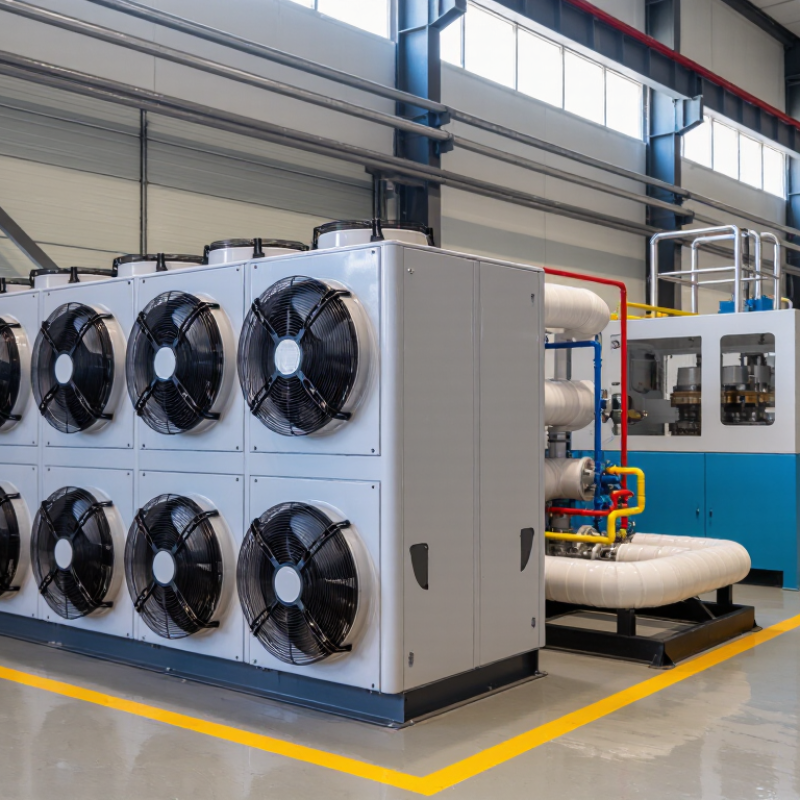
What an Air-Cooled Process Chiller Is
An air-cooled process chiller removes heat from a circulating liquid and releases it into the surrounding air. The liquid, often water or a water-and-glycol mixture, travels through equipment that needs steady cooling. A pump sends the warmed fluid back to the chiller, where it is cooled again. Air moves constantly. Fans draw outdoor air across condenser coils, helping refrigerant carry heat away from the process loop.
This arrangement avoids the cooling tower and its water-treatment demands, which can simplify installation. It still needs clear airflow around the unit. Placing it beside a hot exhaust outlet or in a cramped enclosure can reduce performance, especially on a warm afternoon. That matters. Chiller capacity should match the actual heat load, required fluid temperatures, and local design conditions—not just a machine’s headline rating. In practice, dust on coil fins can also restrict heat transfer, so inspection and cleaning belong in routine maintenance. An air-cooled unit may use more power than a water-cooled alternative in some conditions; the difference depends on climate, load, and system design. The trade-off is not always obvious from the equipment alone.
How an Air-Cooled Process Chiller Removes Heat
An air-cooled process chiller removes heat from a circulating liquid and releases it into the surrounding air. A pump sends warm process fluid through the chiller’s evaporator. There, heat crosses a metal surface into the refrigerant. The refrigerant absorbs that energy and changes from liquid to vapor. The cooled process fluid then returns to equipment such as a molding machine or production line.
The refrigerant vapor moves to the compressor, which raises its pressure and temperature. It then flows through a finned condenser coil. Fans draw ambient air across the coil, carrying heat away from the refrigerant. As it cools, the refrigerant condenses back into liquid. An expansion device lowers its pressure before it returns to the evaporator. The cycle repeats. Heat leaves here.
Airflow affects performance more than a casual inspection might suggest. Dust on coil fins, blocked vents, or hot exhaust air recirculating into the intake can reduce heat rejection. A chiller may still run, but struggle to hold its setpoint during warm weather. Regularly checking coil cleanliness, fan operation, fluid flow, and temperature readings helps reveal problems early. Sizing also matters: an undersized unit may not keep up with changing process loads. In practice, actual conditions can be less tidy than a specification sheet implies.
What Is an Air Cooled Process Chiller? - How an Air-Cooled Process Chiller Removes Heat
| Stage or Component |
What Happens |
Heat Flow |
Practical Detail |
| Process-fluid return |
Fluid warmed by equipment or a manufacturing process returns to the chiller. |
Heat travels from the process into the returning fluid. |
The fluid may be water or a compatible water-based mixture, depending on the system and operating conditions. |
| Evaporator |
The process fluid passes through a heat exchanger, where it transfers heat to the refrigerant. |
Heat moves from the process fluid to the refrigerant. |
The refrigerant absorbs heat and evaporates at a lower pressure. The two fluids remain separated by the heat-exchanger surfaces. |
| Compressor |
The compressor draws in refrigerant vapor and compresses it to a higher pressure. |
Energy is added to the refrigerant, raising its pressure and temperature. |
The compressor drives refrigerant circulation through the refrigeration cycle. |
| Air-cooled condenser |
Hot, high-pressure refrigerant releases heat through condenser coils as fans move outdoor air across them. |
Heat moves from the refrigerant into the surrounding air. |
The refrigerant condenses into a liquid. Condenser airflow and outdoor temperature affect heat rejection. |
| Expansion device |
Liquid refrigerant passes through an expansion device before returning to the evaporator. |
Refrigerant pressure and temperature decrease before it absorbs more process heat. |
The device regulates refrigerant flow to support the operating conditions of the system. |
| Chilled-fluid supply |
The cooled process fluid leaves the evaporator and circulates back to the equipment or process. |
The fluid carries heat away from the process on its next pass. |
A pump and piping form the process-fluid loop; actual fluid temperatures depend on the application and chiller design. |
| Continuous heat removal |
The refrigeration cycle repeats while cooling is required. |
Heat is transferred from the process fluid and ultimately discharged to ambient air. |
Unlike a water-cooled chiller, an air-cooled unit rejects condenser heat directly to air and does not require a cooling tower for that purpose. |
In summary: An air-cooled process chiller removes heat from a circulating process fluid in the evaporator, moves that heat through a refrigerant circuit, and releases it outdoors through a fan-assisted condenser. Capacity and operating performance vary with the chiller design, process conditions, airflow, and ambient temperature.
Key Components and Their Functions
An air-cooled process chiller removes heat from a circulating fluid and rejects it to surrounding air. Its compressor raises refrigerant pressure and temperature, allowing heat to move through the refrigeration circuit. The evaporator transfers heat from process water or glycol into the refrigerant. Fouling or poor fluid flow can reduce heat transfer. Even a clean-looking system may need closer inspection.
The condenser coil releases captured heat outdoors. Fans pull ambient air across its fins, so blocked clearance or dusty surfaces can raise condensing temperature. An expansion valve meters refrigerant into the evaporator, matching flow to changing load. A circulation pump sends chilled fluid through equipment, while a reservoir can buffer brief demand swings. Sensors and controls monitor temperature, pressure, and flow, then adjust operation or trigger alarms.
Small details matter.
A sensor mounted in the wrong spot may report a tidy number that does not represent the process. During routine checks, compare fluid temperatures at the chiller inlet and outlet, and inspect airflow around the coil. The layout is not always as clean in real installations.
During selection, check the required fluid temperature, heat load, ambient conditions, and allowable flow range; published capacity alone can be misleading.
Common Air-Cooled Chiller Configurations
Common Air-Cooled Chiller Configurations
Air-cooled process chillers commonly come as self-contained packaged units. The compressor, evaporator, condenser, and controls share one cabinet. Install the unit outdoors or in a well-ventilated service area, then connect the process piping and power. Simple to deploy. Hot exhaust air needs room to escape; tight enclosures can raise operating temperatures and reduce cooling capacity.
A split configuration places the evaporator and controls near the process, while the air-cooled condenser sits remotely. This can help when floor space is limited or condenser noise should be kept away from operators. Refrigerant piping length and elevation matter, though. Poor routing can complicate commissioning and affect performance. A split layout is not automatically the better choice.
Modular systems use several smaller chiller circuits instead of one large machine. They can follow changing loads, and one module may remain available during maintenance if the system is designed for it. But staging controls, water flow, and minimum system volume must work together. Small details count. A buffer tank can reduce rapid cycling when demand swings, while pumps and strainers support steady flow. Compare peak heat load, summer ambient temperature, clearance, and service access before choosing. Real plants rarely behave exactly like a design spreadsheet, so check startup surges and overnight low loads too.
What Is an Air-Cooled Process Chiller?
Common Air-Cooled Chiller Configurations
An air-cooled process chiller removes heat from a process fluid and rejects it to outdoor air through a condenser coil and fans. Packaged units may use one or more refrigerant circuits; modular systems combine multiple units. The circuit counts shown are illustrative configuration examples, not industry-wide standards. Actual layouts vary by cooling capacity and design.
Industrial Applications and Operating Considerations
An air-cooled process chiller removes heat from circulating liquid and releases it into the surrounding air. In factories, that liquid may cool a laser cutter, injection-molding machine, packaging line, or food-processing equipment. Heat must go somewhere. Fans move outdoor air across condenser coils, so these chillers can suit sites without cooling towers or a dependable water supply. The right unit depends on the process, not just the room size. A machine with brief, intense heat spikes may need different capacity from one running steadily all shift.
Operating conditions can change performance. Check the required fluid temperature, flow rate, and peak heat load, then consider the hottest expected outdoor temperature. Keep the air intake and exhaust clear; a layout can look spacious on a drawing and still trap hot air. Dust, fibers, and grease on coils restrict airflow, so inspection and cleaning belong in the maintenance schedule. Small details matter. If glycol is needed for freeze protection, confirm its concentration and account for its effect on heat transfer and pump demand. Monitor fluid levels, temperatures, and alarms during normal production, not only during commissioning. In practice, load estimates can be imperfect, and a chiller that seems adequate during a quiet test may struggle when several machines run together.
Conclusion
An Air Cooled Process Chiller is a cooling system that removes heat from a process fluid, such as water or a water-based solution, and releases that heat into the surrounding air. It circulates refrigerant through an evaporator, compressor, condenser, and expansion device. As the refrigerant absorbs heat from the process fluid, it carries that energy to the air-cooled condenser, where fans move ambient air across the coils to disperse the heat. Pumps and controls help maintain fluid flow and regulate operating conditions.
Air-cooled chillers may be packaged as self-contained units or arranged in modular configurations to suit different cooling loads and installation needs. They are used in industrial processes where reliable temperature control supports equipment performance and product consistency. When selecting and operating a system, consider cooling capacity, ambient temperature, airflow clearance, fluid requirements, energy use, and routine maintenance. These factors help the chiller operate efficiently and provide dependable process cooling.